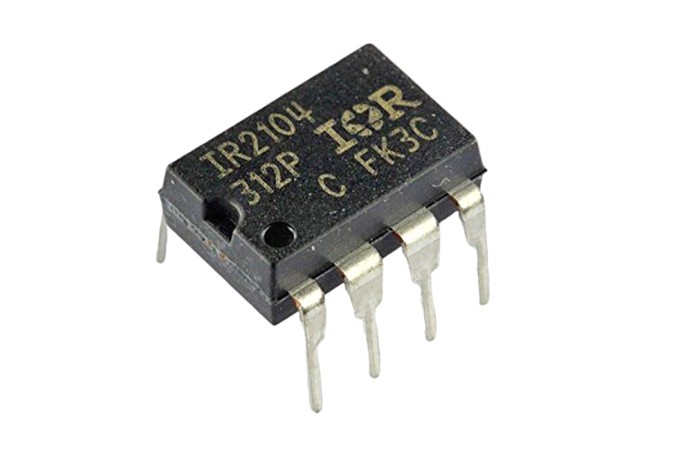
What is IR2104 Half-Bridge Driver?
IR2104 Functional Block Diagram
IR2104 MOSFET Simplified Circuit Diagram
Recommended Operating Conditions
In the intricate world of semiconductor integrated circuits, where innovation meets practicality, the H-bridge configuration stands tall as a cornerstone for driving loads efficiently across a spectrum of devices. At the forefront of this technological landscape stands the venerable IR2104 driver, a stalwart in the realm of power electronics. Renowned for its robust features and unwavering performance, the IR2104 embodies excellence in driving amplified currents from low-power inputs with precision and reliability.
With high voltage and current ratings serving as its hallmark, the IR2104 driver offers a league of advanced features tailored to meet the demands of rigorous applications. Its precise Pulse-Width Modulation (PWM) input characteristics, coupled with efficient dead time control, empower engineers to navigate complex power systems with finesse and accuracy. However, the allure of the IR2104 transcends mere specifications; its ability to seamlessly operate in bootstrap mode elevates it to a position of unrivaled versatility, a coveted asset in the arsenal of engineers crafting high-performance power infrastructures.
In this comprehensive exploration, we embark on a journey into the heart of the IR2104 half-bridge driver, unraveling its intricacies through an in-depth analysis of its specifications, pinout configuration, circuit diagrams, and more. From fundamental principles to practical applications, let us unravel the mysteries of the IR2104 IC, providing you with a holistic understanding of its prowess in reshaping the landscape of power electronics.
What is IR2104 Half-Bridge Driver?
The IR2104 is a high-voltage, high-speed power MOSFET and IGBT driver IC designed specifically for driving half-bridge configurations in applications such as motor controls, inverters, and switching power supplies. Here is an overview of the IR2104 Half-Bridge Driver:
IR2104 Half-Bridge Driver Overview:
- Manufacturer: Infineon Technologies (previously International Rectifier)
- Functionality: Half-Bridge Driver
- Package Type: Typically available in various packages like PDIP, SOIC, and DFN
- Gate Driver: Provides drive signals to control the high-side and low-side power switches in a half-bridge configuration
- Applications: Widely used in motor control systems, power inverters, and other high-power applications
Key Features of IR2104:
-
High Voltage Operation:
- Capable of driving high-voltage power MOSFETs and IGBTs.
- Supports driving power stages in applications requiring high voltage operation.
-
Half-Bridge Configuration:
- Specifically designed to drive the two switches (high-side and low-side) in a half-bridge circuit.
- Enables efficient switching and control of power flows in motor control and power conversion applications.
-
Bootstrap Circuit Integration:
- Typically includes a bootstrap circuit to provide the high-side gate driver with the necessary voltage to turn on the high-side switch efficiently.
- Ensures proper gate drive levels for high-side switching without using an additional isolated power supply.
-
High-Speed Performance:
- Offers fast switching times to enable efficient operation at high frequencies.
- Helps in minimizing switching losses and enhancing system efficiency.
-
Protection Features:
- Often includes various protection mechanisms such as overcurrent protection, undervoltage lockout, and thermal shutdown.
- Safeguards the IC and the connected power switches from damage under fault conditions.
-
Compatible with Different Power Devices:
- Suitable for a wide range of power semiconductor devices like MOSFETs and IGBTs.
- Provides flexibility in choosing power switches based on the specific application requirements.
Typical Applications of IR2104:
- Motor Control: Used in motor drives for controlling the speed and direction of motors.
- Power Inverters: Employed in DC/AC inverters for converting DC power to AC power in applications like solar inverters.
- Switched-Mode Power Supplies (SMPS): Utilized in high-efficiency power supplies for regulating voltage levels.
- Industrial Automation: Integrated into industrial control systems for precise control of power circuits.
Working Principle:
- In a half-bridge configuration, the IR2104 drives the high-side and low-side power switches alternately to control the flow of current through the load (such as a motor or an inverter).
- It generates the necessary gate drive signals to turn on and off the power switches with optimal timing to prevent shoot-through and ensure efficient operation.
- The bootstrap circuit provides the high-side gate driver with a voltage level higher than the supply voltage to drive the high-side switch effectively.
The IR2104 Half-Bridge Driver is a crucial component in various high-power and high-speed applications, providing efficient control and driving capabilities for half-bridge power stages. It plays a significant role in enhancing the performance, efficiency, and reliability of systems utilizing half-bridge power configurations.
Features & Specifications
Features:
-
High Voltage and Current Ratings:
- Capable of driving high-voltage power MOSFETs and IGBTs, making it suitable for a wide range of power applications.
-
Precise Pulse-Width Modulation (PWM) Input:
- Allows for accurate and efficient control of the switching frequency and duty cycle, essential for optimizing power conversion.
-
Efficient Dead Time Control:
- Provides control over the dead time between the turn-off of one switch and the turn-on of the opposite switch, preventing shoot-through currents and improving overall efficiency.
-
Bootstrap Operation Mode:
- Ability to operate in bootstrap mode enhances versatility by enabling efficient high-side gate drive without requiring an isolated power supply.
-
Under-Voltage Lockout (UVLO) Protection:
- Ensures reliable operation by preventing the IC from functioning when the supply voltage is below a specified level.
-
Overcurrent Protection:
- Safeguards the IC and connected components by detecting and limiting excessive current flow.
-
Integrated Shoot-Through Protection:
- Prevents both high-side and low-side MOSFETs from conducting simultaneously, reducing the risk of damaging the components.
-
Fast Propagation Delays:
- Enables high-speed operation, crucial for applications requiring quick switching and response times.
-
Wide Supply Voltage Range:
- Supports a broad range of supply voltages, enhancing compatibility with various power systems.
-
Thermal Shutdown Protection:
- Protects the IC from overheating by disabling operation when the temperature exceeds the specified limit.
Specifications:
-
Supply Voltage Range: Typically supports a wide range, such as 10V to 20V, accommodating various system requirements.
-
Output Peak Current:
- High peak output current capability to drive power switches effectively.
-
Operating Temperature Range:
- Suitable for diverse environmental conditions with an operational range typically from -40°C to +125°C.
-
Package Type:
- Available in industry-standard packages like PDIP, SOIC, DFN, offering flexibility in design and layout.
-
Gate Driver Voltage:
- Provides the necessary gate drive voltage to ensure efficient switching of power MOSFETs and IGBTs.
-
Maximum PWM Frequency:
- Specifies the maximum achievable PWM frequency for precise control in various applications.
-
Output Resistance:
- Low output resistance for efficient power transfer and minimal power dissipation.
-
Propagation Delay:
- Indicates the time delay between the input signal and the output drive to the gate of the power device.
-
Supply Current:
- Specifies the current consumed by the IC during normal operation.
-
Voltage Regulator Integration:
- Some variants may include an integrated voltage regulator to provide stable voltage levels for the gate driver circuitry.
| Type | Parameter |
| Average load current | 10amps |
| Peak current | 20amps |
| VCC voltage range | 12V ~ 36V DC |
| Logic gate voltage supply | 12-15V DC |
| Content of compatible input signals | 3.3V-15V |
| Fully operational | +600V |
| Gate drive supply range | from 10 to 20V |
| Operating Temperature | -40°C~150°C TJ |
| Pinout | SMD-based design |
| Package | 8-DIP |
These features and specifications collectively position the IR2104 as a versatile and reliable solution for driving half-bridge configurations in a myriad of power electronics applications, offering advanced control and protection mechanisms to ensure optimal performance and longevity of the system components.
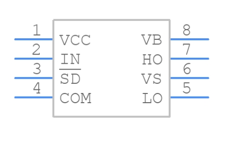
IR2104 Pinout
The IR2104 is a half-bridge driver IC essential in power electronics applications, particularly in driving power MOSFETs and IGBTs. The pinout configuration of the IR2104 is crucial for understanding its connectivity and functionality within a circuit. Below is a typical pinout diagram and description for the IR2104 IC:
IR2104 Pinout Configuration:
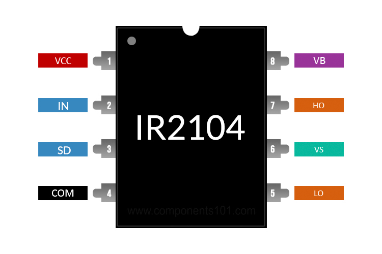
Pin Descriptions:
-
HO (High Output):
- Drives the gate of the high-side power switch in the half-bridge configuration.
-
VS (High Side Floating Supply Voltage Input):
- Connects to a bootstrap capacitor for providing voltage to the high-side gate driver.
-
VB (High Side Floating Output Voltage):
- Output of the high-side gate driver, typically connected to the gate of the high-side power switch.
-
SHDN (Shutdown Pin):
- Used to enable or disable the IC. When pulled low, the IC shuts down.
-
VSS (Ground):
- Connects to the ground reference of the system.
-
SD (Shutdown Delay Pin):
- Input for setting the shutdown delay of the IC in conjunction with an external capacitor.
-
COM (Common Pin):
- Common connection for the low-side gate driver output and other internal circuits.
-
HO (High Output):
- Alternative description for pin 1, indicating the gate drive output for the high-side switch.
-
HIN (High Input):
- PWM input for controlling the high-side gate driver.
-
LIN (Low Input):
- PWM input for controlling the low-side gate driver.
-
VCC (Supply Voltage Input):
- Connects to the power supply voltage of the IC.
-
VB (Low Side Floating Output Voltage):
- Output of the low-side gate driver, typically connected to the gate of the low-side power switch.
-
VB (Low Side Floating Supply Voltage Input):
- Connects to a bootstrap capacitor for providing voltage to the low-side gate driver.
-
LO (Low Output):
- Drives the gate of the low-side power switch in the half-bridge configuration.
Pinout Summary:
- High-Side and Low-Side Outputs: HO and LO are the gate drive outputs for the high-side and low-side power switches, respectively.
- Shutdown and Control Inputs: SHDN, SD, HIN, and LIN pins offer control over the IC's operation and features.
- Supply Voltage and Ground Connections: VCC, VS, VSS, and COM provide the necessary power and reference connections for the IC.
Understanding the IR2104 pinout is crucial for correctly implementing it in a circuit design, ensuring proper connections and functionalities for driving power switches effectively in half-bridge configurations.
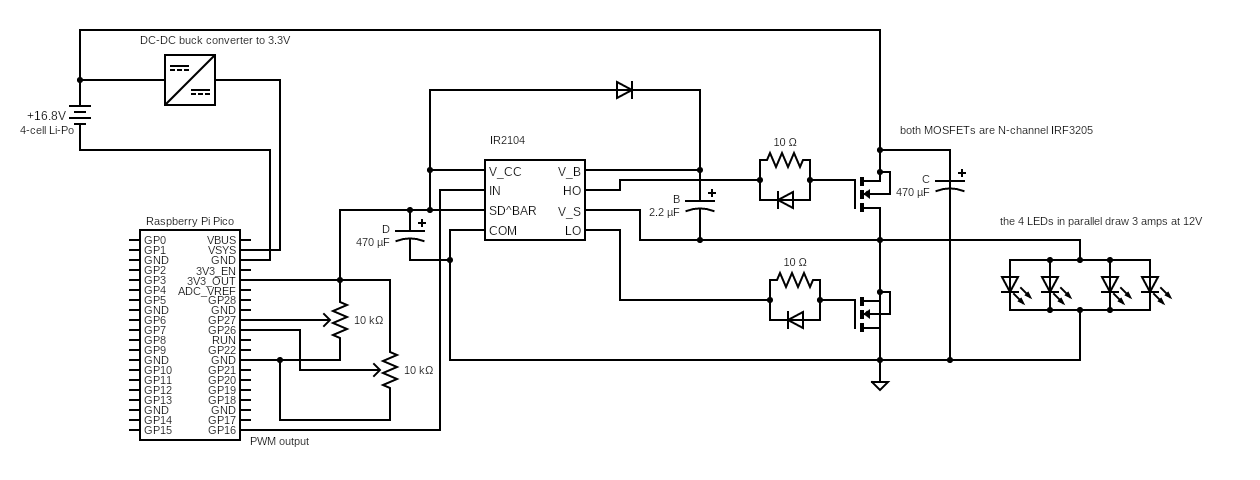
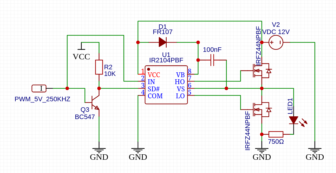
IR2104 Typical Schematic
.png)
IR2104 Functional Block Diagram
IR2104 MOSFET Simplified Circuit Diagram
IR2104 Equivalent
DGD2104, IR2103, IRS2104, IR2153 and IR2110 can be equivalent to IR2104.
How to use IR2104
Utilizing the IR2104 half-bridge driver effectively in your circuit requires an understanding of its features, pinout configuration, and the specific requirements of your application. Here's a general guide on how to use the IR2104 in a typical half-bridge configuration:
Steps to Use the IR2104 in a Circuit:
1. Design Considerations:
- Determine the power requirements, switching frequency, and control needs of your application.
- Select appropriate power MOSFETs or IGBTs that are compatible with the IR2104's drive capability and your system requirements.
2. Circuit Connection:
- Connect the VCC pin of the IR2104 to the supply voltage (typically 10V to 20V).
- Connect the VS pin to a bootstrap capacitor for the high-side gate driver voltage.
- Connect COM and VSS pins to the ground reference of your system.
3. Gate Driver Connections:
- Connect the HIN pin to the PWM signal source for controlling the high-side switch.
- Connect the LIN pin to the PWM signal source for controlling the low-side switch.
4. Power Switch Connections:
- Connect the HO and LO outputs of the IR2104 to the gates of the high-side and low-side power switches, respectively.
- Connect the sources of the power switches to the system ground.
5. Bootstrap Capacitor:
- Size and select the bootstrap capacitor according to the application requirements to ensure stable high-side gate driver operation.
6. Shutdown and Control:
- Use the SHDN pin to enable or disable the IC as needed.
- Set the shutdown delay using an external capacitor connected to the SD pin, if required.
7. Input Signal Considerations:
- Ensure that the PWM signals provided to HIN and LIN meet the timing and voltage levels specified in the IR2104 datasheet.
8. Protection and Testing:
- Implement external protection circuits as necessary, such as overcurrent protection.
- Test the circuit under varying load conditions to validate performance and efficiency.
9. Thermal Considerations:
- Monitor the temperature of the IR2104 during operation to prevent overheating.
- Ensure adequate thermal dissipation for the driver IC.
10. Performance Optimization:
- Fine-tune the PWM signals and dead times to optimize the efficiency and switching performance of the half-bridge configuration.
11. Review the Datasheet:
- Refer to the IR2104 datasheet for detailed information on functionality, timing diagrams, application circuits, and specific recommendations from the manufacturer.
By following these steps and considering the guidelines outlined in the datasheet, you can effectively use the IR2104 half-bridge driver in your circuit design, enabling precise control and efficient operation of power switches in various high-power applications.
Absolute Maximum Ratings
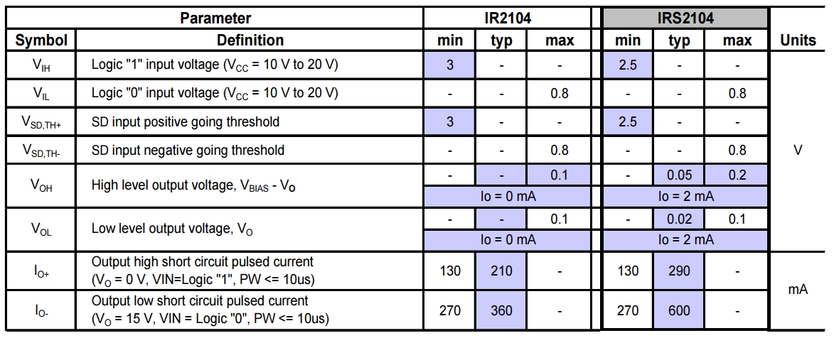
Recommended Operating Conditions
When working with the IR2104 half-bridge driver IC, it is crucial to operate within its recommended operating conditions to ensure optimal performance, reliability, and longevity of the device. Here are the typical recommended operating conditions for the IR2104:
1. Supply Voltage (VCC):
- Recommended Range: Typically 10V to 20V
- Ensure that the supply voltage stays within this range to guarantee proper functionality of the IC.
2. Operating Temperature:
- Recommended Range: -40°C to +125°C
- Operate the IR2104 within this temperature range to maintain stability and prevent damage due to extreme temperatures.
3. Input Voltage Levels (HIN, LIN):
- Recommended Levels: Comply with the specifications provided in the datasheet.
- Ensure that the input voltage levels applied to the control pins (HIN, LIN) meet the requirements outlined in the datasheet for proper operation.
4. PWM Frequency:
- Maximum Frequency: Check the datasheet for the maximum PWM frequency supported by the IR2104.
- Operating the IC within the specified PWM frequency range ensures accurate switching and control.
5. Bootstrap Capacitor Selection:
- Selection Criteria: Refer to the datasheet for guidance on selecting the appropriate bootstrap capacitor.
- Choose a bootstrap capacitor that meets the recommended specifications to ensure stable high-side gate driver operation.
6. Power Switch Compatibility:
- Selection Criteria: Use power MOSFETs or IGBTs compatible with the IR2104's drive capabilities.
- Ensure that the power switches can handle the voltage, current, and switching characteristics of your application.
7. Dead Time Control:
- Optimization: Adjust the dead time between the high-side and low-side switches for optimal performance.
- Proper dead time control helps prevent shoot-through currents and enhances overall efficiency.
8. Thermal Management:
- Heat Dissipation: Implement adequate thermal management to prevent overheating of the IC.
- Ensure proper heat sinking or cooling mechanisms to maintain the IR2104 within its operating temperature limits.
9. Protection Circuits:
- Recommended: Implement overcurrent protection and other relevant safety features for device and system protection.
- Include safeguards to protect the IC from faults and ensure reliable operation.
10. Shutdown Control:
- Usage: Utilize the SHDN pin for enabling or disabling the IC as needed.
- Implement proper shutdown control mechanisms in your application where required.
IR2104 Applications
The IR2104 is a versatile half-bridge driver IC commonly used in a variety of power electronics applications where precise control of high-voltage power switches like MOSFETs or IGBTs is required. Here are some common applications where the IR2104 is utilized:
1. Switching Power Supplies:
- IR2104 is often used in the driver stage of switching power supplies, such as isolated DC-DC converters, where efficient switching of power devices is essential for regulating voltage and current levels.
2. Motor Drives:
- In motor control applications, the IR2104 can drive the power switches in motor drive circuits, providing the necessary gate drive signals for controlling the speed and direction of motors.
3. Inverters:
- IR2104 is employed in inverter circuits for converting DC power to AC power in applications like solar inverters, UPS systems, and motor drives.
4. Lighting Systems:
- LED drivers and lighting control systems benefit from the precise switching capabilities of the IR2104, enabling efficient regulation of light output.
5. Switched-Mode Power Supplies (SMPS):
- In various types of SMPS designs, including flyback, forward, and half-bridge configurations, the IR2104 ensures smooth and efficient operation.
6. Battery Chargers:
- IR2104 is used in battery charging circuits to control the charging process efficiently and protect the battery from overcharging or damage.
7. Uninterruptible Power Supplies (UPS):
- UPS systems rely on the IR2104 for driving power switches that manage the transfer of power sources during outages and ensure a continuous power supply to connected devices.
8. Resonant Converters:
- Resonant converter topologies, such as LLC and ZVS converters, benefit from the high-speed switching capabilities of the IR2104 for improved efficiency and reduced switching losses.
9. Induction Heating:
- IR2104 is used in induction heating systems where high-frequency switching is required to generate intense heat for various industrial applications.
10. Welding Equipment:
- Welding machines often utilize the IR2104 for driving power switches in the welding circuit to control the power delivery during welding operations.
11. Power Factor Correction (PFC) Circuits:
- PFC circuits that improve power efficiency in AC-DC power supplies employ the IR2104 for precise control of the power switch.
12. Renewable Energy Systems:
- Solar inverters and wind turbine systems utilize the IR2104 for efficient power conversion and control, making them integral components of renewable energy systems.
13. Automotive Applications:
- In automotive electronics, the IR2104 can be found in systems like onboard chargers, motor drives, and power management units where robust and efficient power control is essential.
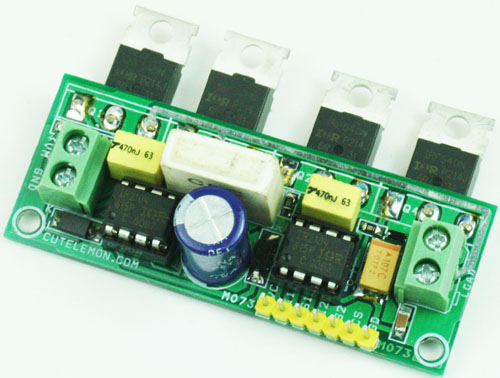
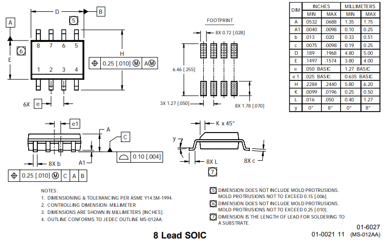
IR2104 Package
IR2104 Datasheet
Download IR2104 Datasheet PDF.
IR2104 vs. IR2101
IR2104 |
IR2101 |
|
| Rohs Code | No | No |
| Part Life Cycle Code | Not Recommended | Not Recommended |
| Ihs Manufacturer | INFINEON TECHNOLOGIES AG | INFINEON TECHNOLOGIES AG |
| Package Description | DIP-8 | DIP-8 |
| Reach Compliance Code | compliant | compliant |
| ECCN Code | EAR99 | EAR99 |
| HTS Code | 8542.39.00.01 | 8542.39.00.01 |
| kg CO2e/kg | 12.04 | 12.04 |
| Average Weight (mg) | 569.675 | 569.675 |
| CO2e (mg) | 6858.887 | 6858.887 |
| Samacsys Manufacturer | Infineon | Infineon |
| High Side Driver | YES | YES |
| Input Characteristics | SCHMITT TRIGGER | SCHMITT TRIGGER |
| Interface IC Type | HALF BRIDGE BASED MOSFET DRIVER | HALF BRIDGE BASED MOSFET DRIVER |
| JESD-30 Code | R-PDIP-T8 | R-PDIP-T8 |
| JESD-609 Code | e0 | e0 |
| Length | 9.88 mm | 9.88 mm |
| Number of Functions | 1 | 1 |
| Number of Terminals | 8 | 8 |
| Operating Temperature-Max | 125 °C | 125 °C |
| Operating Temperature-Min | -40 °C | -40 °C |
| Output Characteristics | TOTEM-POLE | TOTEM-POLE |
| Output Peak Current Limit-Nom | 0.36 A | 0.36 A |
| Output Polarity | TRUE | TRUE |
| Package Body Material | PLASTIC/EPOXY | PLASTIC/EPOXY |
| Package Code | DIP | DIP |
| Package Shape | RECTANGULAR | RECTANGULAR |
| Package Style | IN-LINE | IN-LINE |
| Peak Reflow Temperature (Cel) | NOT SPECIFIED | NOT SPECIFIED |
| Qualification Status | Not Qualified | Not Qualified |
| Seated Height-Max | 5.33 mm | 5.33 mm |
| Supply Voltage-Max | 20 V | 20 V |
| Supply Voltage-Min | 10 V | 10 V |
| Supply Voltage-Nom | 15 V | 15 V |
| Supply Voltage1-Max | 620 V | 620 V |
| Supply Voltage1-Min | 5 V | 5 V |
| Surface Mount | NO | NO |
| Technology | CMOS | CMOS |
| Temperature Grade | AUTOMOTIVE | AUTOMOTIVE |
| Terminal Finish | Tin/Lead (Sn/Pb) | Tin/Lead (Sn/Pb) |
| Terminal Form | THROUGH-HOLE | THROUGH-HOLE |
| Terminal Pitch | 2.54 mm | 2.54 mm |
| Terminal Position | DUAL | DUAL |
| Time@Peak Reflow Temperature-Max (s) | NOT SPECIFIED | NOT SPECIFIED |
| Turn-off Time | 0.22 µs | 0.22 µs |
| Turn-on Time | 0.82 µs | 0.22 µs |
| Width | 7.62 mm | 7.62 mm |
| Base Number Matches | 7 | 13 |
difference
IR2104 |
IR2101 |
|
| Turn-on Time | 0.82 µs | 0.22 µs |
| Base Number Matches | 7 |
13 |
| IR2104 | IR2101 | |
| Package | SOIC-8 | DIP-8 |
| Driver | 600V 2-OUT | High and Low Side |
| Logic input compatible | Standard CMOS or LSTTL | N/A |
Conclusion
The IR2104 half-bridge driver IC is a crucial component in power electronics applications where precise control and efficient switching of high-voltage power devices like MOSFETs and IGBTs are required. With its robust features, specifications, and recommended operating conditions, the IR2104 offers a versatile and reliable solution for a variety of applications across different industries.
Key Points about the IR2104:
-
Versatile Functionality: The IR2104 is commonly used in applications such as motor drives, inverters, power supplies, lighting systems, and more, where precise control of power switches is essential.
-
High-Performance Features: Features like dead time control, under-voltage lockout protection, overcurrent protection, and integrated shoot-through protection enhance the IC's performance and reliability.
-
Operating Conditions: Adhering to recommended operating conditions, including supply voltage range, operating temperature, input voltage levels, and PWM frequency, ensures optimal performance and longevity of the IC.
-
Broad Applications: The IR2104 finds applications in diverse fields like automotive, renewable energy, welding equipment, UPS systems, and more, showcasing its adaptability and efficiency in various power electronics systems.
-
Safety and Protection: Incorporating protection circuits, careful dead time control, and thermal management strategies can enhance system safety and reliability when using the IR2104.
In conclusion, the IR2104 serves as an indispensable component in modern power electronics designs, playing a vital role in enabling efficient power conversion, motor control, and various voltage regulation tasks. By understanding its features, specifications, operating conditions, and applications, engineers and designers can leverage the IR2104 to create high-performance, reliable, and energy-efficient systems across a wide range of industries.
FAQ
What is IR2104 used for?
The IR2104 is suitable for driving high-power switching devices such as MOSFETs and IGBTs, and it can drive both high-side and low-side MOSFETs.
What is half bridge gate driver?
Half-bridge gate drivers are high-voltage, high-speed gate drivers designed to drive N-channel MOSFETs and IGBTs.
What is the difference between IRS2104 and IR2104?
The IRS2104 features faster rise and fall times compared to the IR2104.
Why is IR2104 MOSFET driver not working?
To enable the chip, you should keep the SD pin high. However, if you were properly activating the SD pin (which you currently aren't), you would need to include a base resistor. Without this base resistor, the IN input cannot exceed approximately 0.7 volts, which is unlikely to activate the IR2104.
What is the difference between a full bridge and half bridge gate driver?
Half-bridge drivers incorporate one low-side and one high-side driver, enabling them to drive Q1 and Q2 (or Q3 and Q4) simultaneously. Full-bridge drivers, on the other hand, include two low-side and two high-side drivers, allowing them to drive all four FETs.